Structured text is one of the three most popular languages supported by IEC61131-3 along with Ladder Logic and Continuous Function Chart. While there are several advantages to ST, there are also some limitations which I believe are worth noting. For one,
- it can be quite difficult to follow for fault finding purposes and two,
- it can be intimidating or near impossible for non-programmers to follow and debug because it lacks visual representation.
However I say this with a grain of salt because while Ladder Logic and Function Charts may be ideal for small programs, ST is far more readable and reliable when implementing programs that are much more complex. It also provides methods which make it easy to implement loops, array manipulation, and state machines.
Those with a computer science background will find ST familiar as it is similar to traditional programming language such as C and Python.
Ideally, a PLC programmer should be able to utilise all languages offered in the IEC61131-3 if they want to be an efficient programmer.
Converting Ladder Logic to Structured Text
If you have already worked with ladder logic ,the easiest way to familiarise yourself to ST is by looking at the equivalent ladder logic program.
Ladder logic can be interpreted as a collection of if-else statements replaced with contacts and coils for electricians who are not familiar with programming. Structured Text is just the text version of that representation.
ST programs are executed line to line, common to scripting languages such as VBScript, C# and Python.
Implementation
Example 1: Contacts and Coils
Ladder Logic:

Structured Text:
IF BIT1 THEN
	COIL1 := TRUE;
ELSE
	COIL1 := FALSE;
END_IF
COIL1 is TRUE if and only if BIT1 is TRUE
Example 2: SET & RESET Coils
Ladder Logic:

Structured Text:
IF BIT1 THEN
	COIL1 := TRUE;
ELSIF BIT2 THEN
	COIL1 := FALSE;
END_IF
A TRUE state of BIT1 will latch COIL1 to TRUE.
A TRUE state of BIT2 will latch COIL1 to FALSE.
If neither conditions are TRUE, COIL1 will hold the last value that was written to it
Example 3: Timers
Ladder Logic:

Structured Text:
TON1(IN := BIT1, PT := T#1s, Q => COIL1);If BIT1 is TRUE timer TON1 begins. After 1 second, outpoint COIL1 is True.
IF BIT1 is FALSE, the Timer resets back to 0 and output COIL1 is False
Example 4: R_TRIG (Rising Edge Trigger)

R_TRIG1(CLK := BIT1, Q => COIL1);R_TRIG emulates a “click” action in the PLC. When BIT1 transitions from FALSE to TRUE, COIL1 is TRUE for one PLC scan cycle.
Putting it together
Without going into any further detail, lets go through one real world example program to show how we can implement it structured text.
Basic tank level control
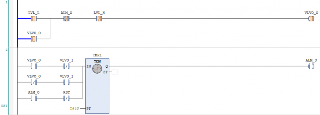
Imagine we have a tank which we want to ensure has sufficient water at all times. We are provided one LOW tank level switch and one HIGH tank level switch, and an OPEN output switch for a water inlet valve with feedback to ensure the valve is open.

An alarm output is latched on if the valve does not open in time which blocks the open command from the PLC. The alarm requires an operator reset before another open command output can be sent from the PLC.
Essentially, the program will block open output during a faulty state, otherwise known as fail to close.
Ladder Logic:

Implementation in Structured Text
VAR
	VLVO_O : BOOL; // VALVE OPEN OUTPUT
	VLVO_I : BOOL; // VALVE OPEN FEEDBACK
	LVL_L : BOOL; // VALVE LEVEL LOW SWITCH
	LVL_H : BOOL; // VALVE LEVEL HIGH SWITCH
	TMR1 : TON; // ALARM TIMER
	ALM : BOOL; // ALARM
	RST : BOOL; // OPERATOR RESET
END_VAR
IF (LVL_L OR VLVO_O) AND NOT ALM AND NOT LVL_H THEN
VLVO_O := TRUE;
ELSE
VLVO_O := FALSE;
END_IF
TMR1(
IN := (VLVO_O AND NOT VLVO_I) OR
(NOT VLVO_O AND VLVO_I) OR
(ALM AND NOT RST),
PT := T#5S
);
IF TMR1.Q THEN
ALM := TRUE;
ELSE
ALM := FALSE;
END_IFAs you can see from the example above, Structured Text is essentially contacts and coils converted into words. The logic has been copied one for one and works exactly the same in both languages.
Initially we latch the valve on output when we detect the low level switch. We keep it latched unless we detect a level high switch or an alarm is triggered.
The alarm is set to on if we don’t see the corresponding feedback within 5 seconds. The timer is conditioned with
OR (ALM AND NOT RST)to ensure the alarm remains latched on unless the reset button is pressed
Advanced programs simplified in Structured Text
// Calculating the average of three temperature sensors

VAR
	TEMP1 : REAL;
	TEMP2 : REAL;
	TEMP3 : REAL;
	TEMP_ARR : ARRAY[0..3] OF POINTER TO REAL;
	IDX : INT;
	VAL : REAL;
END_VAR
In this program, we define an array of pointers with a length 3 which point to REAL data types. Then we map each temperature sensor to the array.
Finally we loop through the array and dereference each pointer, summing each value and then compute the average.
While this may look like more work for computing the average of three sensors, if there were more sensors 10 or 20+, this method removes the task of manually adding up each sensor. Now you merely define the number of sensors and map those sensors to an array and let the loop compute the sum for you.
Leave a Reply